


Contact us
Company Name: Lanteky Machinery
Address: No 5558 Chuansha Road, Pudong Discrict, Shanghai, China\
Post: 212002
Tel: (+86) 21-60346873
Fax: (+86) 21-60346873
Email: landy.industry20@gmail.com
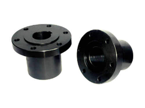
Flange Coupling (YL Series)

Description
Flange coupling is used to bring two half couplings together for the purpose of transmitting movement and torque. It belongs to rigid coupling. This shaft coupling mainly has two structures. The first is to transfer torque by using reamed hole bolt. The second is to achieve centering by the mutual coordinate of bending in one half coupling and groove in another coupling.
Application
Flange coupling is widely used in low speed, shock-free and high rigidity occasions. This shaft coupling belongs to rigid coupling. It is applicable to line shafting of concentric line with 63 to 100000 N.m transmitting torque.
Features
1. The structure of flange coupling is simple, thus it has the advantages of low cost and convenient in installation.
2. Shaft coupling has good rigidity and is able to transfer stronger torque.
3. Flange coupling can be made up of gray cast iron or carbon steel. When it comes to heavy load or the circular velocity is more than 30 m/s, shaft coupling is made up of cast steel or forged steel.
| Model | Nominal Torque Tn (N.m) |
Limited Rotational Speed [n](r/min) | Shaft Hole Diameter d (H7) | Shaft Hole Length L | D | D1 | Bolt | L0 | Rotational Inertia (kg.m2) | Weight (kg) |
|||||
| Y Model | J1 Model | Quantity (n) |
Diameter (m) | ||||||||||||
| Iron | Steel | Steel | Iron | Y Model | J1 Model | ||||||||||
| YL1 YLD1 |
10 | 8100 | 13000 | 10 11 |
10 11 |
25 | 22 | 71 | 53 | 3(3) | M6 | 54 | 48 | 0.0018 | 0.94 |
| 12 14 |
12 14 |
32 | 27 | 68 | 58 | ||||||||||
| 16 18 19 |
16 18 19 |
42 | 30 | 88 | 64 | ||||||||||
| 20 - |
20 22 |
52 | 38 | 108 | 80 | ||||||||||
| YL2 YLD2 |
16 | 7200 | 12000 | 12 14 |
12 14 |
32 | 27 | 80 | 64 | 4(4) | M6 | 68 | 58 | 0.0035 | 1.50 |
| 16 18 19 |
16 18 19 |
42 | 30 | 88 | 64 | ||||||||||
| 20 22 |
20 22 |
52 | 38 | 108 | 80 | ||||||||||
| YL3 YLD3 |
25 | 6400 | 10000 | 14 | 14 | 32 | 27 | 90 | 69 | 3(3) | M8 | 68 | 58 | 0.0060 | 1.99 |
| 16 18 19 |
16 18 19 |
42 | 30 | ||||||||||||
| 88 | 64 | ||||||||||||||
| 20 22- |
20 22 24 |
52 | 38 | 108 | 80 | ||||||||||
| 128 | 92 | ||||||||||||||
| YL4 YLD4 |
40 | 5700 | 9500 | 18 19 |
18 19 |
42 | 30 | 100 | 80 | 3(3) | M8 | 88 | 64 | 0.0093 | 2.47 |
| 20 22 24 |
20 22 24 |
52 | 38 | 108 | 80 | ||||||||||
| 25 - |
25 28 |
62 | 44 | 128 | 92 | ||||||||||
| YL5 YLD5 |
63 | 5500 | 9000 | 22 24 |
22 24 |
52 | 38 | 105 | 85 | 4(4) | M8 | 108 | 80 | 0.013 | 3.19 |
| 25 28 |
25 28 |
62 | 44 | 128 | 92 | ||||||||||
| 30 - |
30 32 |
82 | 60 | 168 | 124 | ||||||||||
| YL6 YLD6 |
100 | 5200 | 8000 | 24 | 24 | 52 | 38 | 110 | 90 | 4(4) | M8 | 108 | 80 | 0.017 | 3.99 |
| 25 28 |
25 28 |
62 | 44 | 128 | 92 | ||||||||||
| 30 32 - |
30 32 35 |
82 | 60 | 168 | 124 | ||||||||||
| YL7 YLD7 |
160 | 4800 | 7600 | 28 | 28 | 62 | 44 | 120 | 95 | 4(3) | M10 | 128 | 92 | 0.029 | 5.66 |
| 30 32 35 38 |
30 32 35 38 |
82 | 60 | 168 | 124 | ||||||||||
| - | 40 | 112 | 84 | 228 | 172 | ||||||||||
| YL8 YLD8 |
250 | 4300 | 7000 | 32 35 38 | 32 35 38 |
82 | 60 | 130 | 105 | 4(3) | M10 | 169 | 125 | 0.043 | 7.29 |
| 40 42 - |
40 42 45 |
112 | 84 | 229 | 173 | 6.53 | |||||||||
| YL9 YLD9 |
630 | 4100 | 6800 | 38 | 38 | 82 | 60 | 140 | 115 | 6(3) | M10 | 169 | 125 | 0.064 | 9.53 |
| 112 | 84 | 229 | 173 | ||||||||||||
| 40 42 45 48 - |
40 42 45 48 50 |
||||||||||||||
| YL10 YLD10 |
630 | 3600 | 6000 | 45 48 50 55 - |
45 48 50 55 56 |
160 | 130 | 6(4) | M12 | 0.112 | 12.46 | ||||
| - | 60 | 142 | 107 | 289 | 219 | ||||||||||
| YL11 YLD11 |
1000 | 3200 | 5300 | 50 55 56 | 50 55 56 |
112 | 84 | 180 | 150 | 8(4) | M12 | 229 | 173 | 0.205 | 17.97 |
| 60 63 65 - |
60 63 65 70 |
142 | 107 | 289 | 219 | ||||||||||
| YL12 YLD12 |
1600 | 2900 | 4700 | 60 63 65 70 71 75 | 60 63 65 70 71 75 |
200 | 170 | 12(6) | M12 | 0.443 | 30.62 | ||||
| - | 80 | 52 | 38 | 349 | 269 | 0.463 | 29.52 | ||||||||
| YL13 YLD13 |
2500 | 2600 | 4300 | 70 71 75 | 70 71 75 |
142 | 107 | 220 | 185 | 8(6) | M16 | 289 | 219 | 0.646 | 35.58 |
| 80 85 - |
80 85 90 |
172 | 132 | 349 | 269 | ||||||||||
| YL14 YLD14 |
4000 | 2300 | 4800 | 80 85 90 95 | 80 85 90 95 |
172 | 132 | 250 | 215 | 12(8) | M16 | 350 | 270 | 1.353 | 57.13 |
| 100 - |
100 110 | 212 | 167 | 430 | 340 | ||||||||||
| YL15 YLD15 |
6300 | 2000 | 3400 | - - |
90 95 |
172 | 132 | 290 | 250 | 12(6) | M20 | 350 | 270 | 2.854 | 89.59 |
| 100 110 120 - |
100 110 120 125 | 212 | 167 | 430 | 340 | ||||||||||
| YL16 YLD16 |
10000 | 1800 | 3000 | - - 120 125 |
100 110 120 125 | 340 | 290 | 12(6) | M24 | 5.271 | 119.57 | ||||
| 130 - |
130 140 | 252 | 202 | 510 | 410 | ||||||||||
| YL17 YLD17 |
14000 | 1600 | 2600 | - - |
120 125 | 212 | 167 | 380 | 330 | 12(6) | M24 | 430 | 340 | 9.139 | 171.71 |
| 130 140 150 | 130 140 150 | 252 | 202 | 510 | 410 | ||||||||||
| - | 160 | 302 | 242 | 610 | 490 | ||||||||||
| YL18 YLD18 |
20000 | 1400 | 2300 | - - |
140 150 | 252 | 202 | 420 | 360 | 12(6) | M30 | 510 | 410 | (17.883) | (263.5) |
| - - - |
160 170 180 | 302 | 242 | 610 | 490 | ||||||||||
Notes
1. The weight and rotational inertia are approximately calculated according toⅠtype shaft coupling with minimum diameter and maximum length.
2. Axle holes with identical type can be randomly combined.
We implement strict quality control system and perfect testing system in order to ensure the quality of shaft couplings. Flange couplings have won widespread praise and recognition by customers both home and abroad.
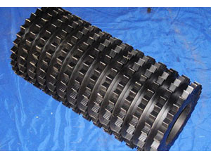
- Feed Roller Feed rollers are provided with special teeth, which are surface hardened by a heat treatment process. We can....
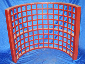
- Chipper Screen Chipper screen is made of heavy rolled steel plates. It is installed at the end of chipping system....